Category Documents

Dimension Essentials

We admit the other dimension post here is completely over-wrought – not that you shouldn’t read it.

Meanwhile here’s a quick and effective how-to:

Framing Plans: General

Rules for framing plans.

A framing plan shows the following:

  1. The framing for the floor of the current story
  2. The load paths of the current story, in black (load-bearing walls, columns, etc).
  3. Supporting walls below the current story
  4. Partitions of the current story, in gray
  5. Plumbing, mechanical, and electrical fixtures that need to be coordinated with the structure, in gray
  6. Dimensions associated with the framing
  7. Layout lines, grid lines, and work lines (a structural grid if you’re using one, otherwise centerlines and alignments communicating design intent).
  8. Detail cross-references to framing and foundation details, and building sections.

Method

  1. Beams and girders. Model them on layer S-frmg.
  2. Joists and rafters. Represent them on the framing plan with 2-d fill 06 | Framing 16 and related fills, on layer S-frmg-2. If you need other spacings, just make another fill. Repetitive members of a floor or roof can be modeled for other reasons, (3d framing diagrams, sections and details) but we don’t typically use the modeled joists and rafters for the framing plan. Why? Because it is far easier and faster to symbolically indicate repetitive framing than to model it accurately enough for use in a floor plan.
  3. Dimensions: Indicate control points – where to start 16″ o.c. spacings.
  4. Partitions. No fill, separators shown.
  5. Bearing Walls. To show a bearing wall, draw a fill on top of it. This is a non-associated, additional element on layer +S-note.
  6. Annotations.
    1. All annotations should go on the layer +S-note.
    2. If you want an annotation to show in the foundation plan simultaneously, use +S-note-all.
    3. Use a background of pen 91 on text blocks to make them readable when placed on fills.
    4. Structure Notes. General notes such as loads, criteria, etc. are part of the General Notes PDF. Specific notes are added to the plans using text blocks.

Dimensions: Ground Rules

“A great building must begin with the unmeasurable, must go through measurable means when it is being designed and in the end must be unmeasurable.”
Louis I. Kahn

Metiendo Vivendum – ‘By Measure We Live’
Motto of Sir Edwin Lutyens

WS

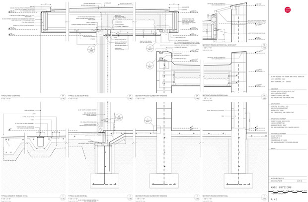
Ground rules for Wall Section sheets.

Layer Set Concept

The model is visible for reference but locked.

Setup

  1. Create wall sections with the section tool, not the detail tool.
  2. [tim: clarify] If the wall section matches a building section, use a hidden section marker layer to create the wall section. Place this marker  in plan directly over the corresponding building section marker at the appropriate wall. The section marker should be on a visible section marker layer if it needs to show in plan.

Drawing References

  1. Use linked detail markers tied to the specific drawing on a Layout.
  2. Source markers may be used to originate a detail but the marker should then be changed to link to a drawing on a layout.

3D

  1. Same as building sections.
  2. Leverage the model as much as possible.
  3. Use the detailing effort to inform the 3D model: unlock the model layers and move 3D elements to keep the model coordinated with the developing details.
  4. Important. Navigate from the view map when starting work in a wall section so the proper layer set locks model elements in the wall section drawing.

2D

  1. Use heavy outlines towards the end of the CD phase once most of the structure and spaces are fully developed.
  2. Lines and fills should be used over the model to convey the necessary amount of detail and scope of work.

download: A 40 WALL SECTION

E, BS, IE

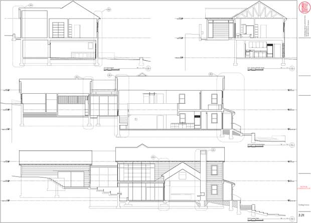
Ground rules for Elevations, Building Sections, and Interior Elevations.
Layer Set Concept

  1. The model is live and unlocked.

Setup

  1. Place section and elevation markers in plan as needed.

Drawing References

  1. Use linked detail markers tied to the specific drawing on a layout.
  2. Do not use source markers for any wall sections as these are developed separately.

3D

  1. Maintain live linked sections to the building model through the life of the project. Remember that appearance of the section is determined both by section attributes of the elements shown, as well as overlay attributes determined by the section tool itself.
  2. Element settings: Utilize element fills cut directly from the model to convey sectional properties.
  3. Section tool settings: Utilize the “uniform pens” settings wherever possible so the overall appearance is consistent.
  4. Profiles are an excellent way to develop an additional level of detail in the building section. They are also handy because they can be updated throughout the life of the project as details develop. Refer to the Profiler Tips and Tricks for some pointers on how to maximize their potential.

2D

  1. Use heavy outlines towards the end of the CD phase once most of the structure and spaces are fully developed.
  2. Add lines and fills as needed to assist with presentation, but utilize the 3D model as much as is sensible.

Floor Plan

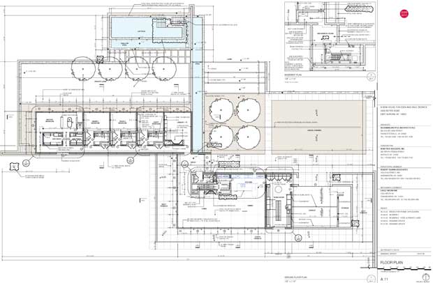
Ground rules for Floor Plans

Layer Set Concept

  1. As many different layer sets as needed to produce drawings.
  2. Different layers and corresponding sets should be used for drawings of a different scale.

3D

  1. If you are drawing an element that will be seen in any other drawing in the set, model it.  This live feedback loop is critical to minimizing mistakes.
  2. Use the graphic control of “model view options”, story display and built-in display functions of library parts to enhance the 2D appearance of the plan as you model the building.
  3. The ArchiCAD library parts are quite good at providing a high level of 2D control.

2D work: Notes, lines, fills, etc…

  1. Exhaust 3D capabilities before you begin to add fills and lines to elements in the model.
  2. Think of 2D work as something static that will live on its own apart from a changing and developing model.
  3. “Model view options” allows a surprisingly high degree of graphic control of the plan view – you may not need to augment at all.
  4. Be sure you have explored all these options before deciding to paint the plans with lots of 2D graphics.  Use composite walls to enhance the amount of detail needed.

download: A 11 FLOOR PLAN